Fluxgate Current Sensors
The Fluxgate technologies cover several types of isolated current sensors and voltage sensors based on the same basic measurement principle: the magnetic field created by the primary current to be measured is detected by a specific sensing element. That sensing element is driven through its B-H loop by a dedicated electronic and the resulting magnetic effects are used for primary current detection. There are a wide variety of methods for concentrating the field, driving the magnetic core, and sensing the field intensity, but in all cases the underlying working principle is the same.
The main types of Fluxgate sensors are:
- The "standard" Fluxgate sensor, smiliar to a closed loop Hall effect design
- The "C-type" Fluxgate, where the performance is significantly improved by:
- Making the field sensing element with the entire toroidal core, without a gap
- Ensuring high frequency performance by using a further core for the transformer effect
- The "IT-type" Fluxgate, where the performance is improved a step further by:
- Duplicating the field sensing element, using two toroidal cores with opposing excitation coils
- Improving the design of the high frequency current transformer and processing electronics
- The "Low frequency" Fluxgate, using only the low frequency part of the "C-type" Fluxgate sensor, to have a cost effective and efficient sensorfor low frequencies
Fluxgate Current Sensors Advantages
Fluxgate current sensors advantages
Fluxgate technology provide low offset & offset drift, thanks to the construction of its magnetic Fluxgate core.
It is also providing excellent accuracy due to the quasi absence of offset. Compared to Hall effect based technologies, this advantage is more noticeable for small currents measurements, where the relative effect of the offset is more significant.
Fluxgate technology benefits from excellent over-current recovery, again because any permanent magnetization of the field sensing element is reset with subsequent B-H cycles (and again, not affecting the main toroid of the "standard" Fluxgate).
It has much higher sensitivity than other technologies, allowing the measurement of very low currents.
With its large dynamic range, Fluxgate current sensors allows for the measurement of both small and large currents with the same transducer.
The sensors also benefits not only from a very high resolution, provided by the low offset, but also from a large temperature range, as the low offset drift make Fluxgate technologies suitable for broader operating temperature ranges (the operational temperature limit is given by the transducer materials and by the components limits).
Last but not least, Fluxgate sensors offer a very extended bandwidth with a very fast response time, provided by the current transformer effect (when relevant) which is further enhanced on C-type and IT-type Fluxgates.
FLUXGATE - CURRENT SENSORS TECHNOLOGIES
Closed Loop Fluxgate CTSR type
Features
- Any kind of AC, DC, pulsed and complex signal
- Non-contact measurement of differential currents
- High accuracy for small residual currents
- Very low drift in temperature (gain and offset)
- Protection against parasitic magnetic field
- Galvanic isolation
Operation principle
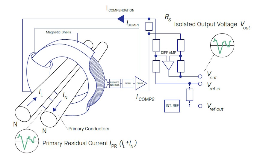
No use of Hall generators. The magnetic flux created by the primary residual current IPR (sum between IL and IN) is compensated by a secondary current. The zero-flux detector is a symmetry detector using a wound core connected to a square-wave generator. The secondary compensating current is an exact representation of the primary current.
In a voltage output transducer, the compensating current is converted to a voltage through a precision resistor, and made available at the output of a buffer amplifier. The magnetic core is actually made up of a pair of 2 magnetic shells inside which the detector is located.
Typical applications of Fluxgate CTSR type current transducers
Closed loop Fluxgate CTSR type current sensors are mainly used in the industrial domain. That technology can also be used in the following applications:
- Drives
- Power supplies
- Failure detection in power sources
- Renewable energies
- Residual current measurement
- Leakage current measurement
- Symmetrical fault detection
- Leakage current detection in stacked DC sources
- Single phase or three phase nominal current measurement up to ±30 A per wire (DC or AC)
- Welding

Closed Loop Fluxgate CAS-CASR-CKSR type
Features
- Any kind of AC, DC, pulsed and complex signal
- High accuracy
- High accuracy in temperature
- Very low drift in temperature (gain and offset)
- Galvanic isolation
- Fast response time
Operation principle
The operating principle can be compared to a current transformer equipped with a magnetic sensing element, which detects the flux density in the core. The output of the field sensing element is used as the error signal in a control loop driving a compensating current through the secondary winding of the transformer.
At low frequencies, the control loop maintains the flux through the core to zero. As the frequency rises, an increased compensating current is required, in order to operate like a current transformer, with a secondary current which is an image of the primary current.
In a presence of a a voltage output sensor, the compensating current is converted to a voltage through a precision resistor, and made available at the output of a buffer amplifier.
Typical applications of Fluxgate CAS, CASR, CKSR type current sensors
Closed loop Fluxgate CAS-CASR-CKSR current sensors have been designed mainly for industrial applications:
- Drives
- AC variable speed and servo motor drives
- Static converters for DC motor drives
- Power supplies
- Uninterruptible Power Supplies (UPS)
- Switched Mode Power Supplies (SMPS)
- Renewable energies
- Solar inverters
- Trackside
- Battery supplied applications

Closed loop Fluxgate ITC type
Features
- Excellent linearity
- Better than Class 0.5R according to EN 50463
- Outstanding long-term stability
- Low residual noise
- Very low sensitivity to high external DC and AC fields
- High temperature stability
Operation principle
ITC current sensors are high accuracy sensors using fluxgate technology. This high sensitivity zero-flux detector uses a second core (D’) to reduce the noise. A difference between primary and secondary current turns creates an asymmetry in the fluxgate current.
This difference is detected by a microcontroller that controls the secondary current that compensates the primary ampere turns (IP x NP).
This results in a very good accuracy and a very low temperature drift.
The secondary compensating current is an exact representation of the primary current.
Typical applications of Fluxgate ITC type
Closed loop Fluxgate ITC type current sensors have been specially designed for the railway environment. They are available for Traction and Industry domains, among other applications areas:
- High Precision
- Traction
- Energy metering
- Propulsion converter
- Substations
- Test and measurement

Closed loop Fluxgate IT type
Features
- Very high global accuracy
- Low residual noise
- Excellent linearity < 1 ppm
- Low cross-over distortion
- High temperature stability
- Wide frequency range
Operation principle
IT current sensors are high accuracy, large bandwidth sensors using fluxgate technology with no Hall generators. The magnetic flux created by the primary current IP is compensated by a secondary current.
The zero-flux detector is a symmetry detector using two further cores connected to a square-wave generator. The secondary compensating current is an exact representation of the primary current.
Typical applications of Fluxgate IT type current transducers
Closed loop Fluxgate IT type sensors are used in the industrial and medical environment. Its ultra-high precision measurement of current provides very high accuracy and excellent linearity in these domains.
Typical applications include:
- High Precision
- Power supplies
- Power analysis
- Test benches
- Laboratory / metrology equipment
- Magnetic Resonance Imaging (MRI)
- Calibration unit
- Precise and high stability inverters
- Energy measurement
- Medical equipment
FLUXGATE - VOLTAGE SENSORS TECHNOLOGIES

Closed loop Fluxgate C type
C-type closed loop Fluxgate sensors are a significant part of the LEM voltage product portfolio. This technology was developed in co-operation with the University of Auckland - New Zealand (Prof. Dan Otto) and provides very high performance in terms of accuracy, temperature drift, bandwidth and response time. This high performance is the result of a patented design used for the compensation of Ampere-turns.
Features
- High accuracy
- Very wide frequency range
- Reduced temperature drift
- Excellent linearity
- Measurement of differential currents (CD)
- Safety isolation (CV)
- Reduced loading on the primary (CV)
Operation principle
This technology uses two toroidal cores and two secondary windings and operates on a fluxgate principle of Ampere-turns compensation.
For the voltage type a small (few mA) current is taken from the voltage line to be measured and is driven through the primary coil and the primary resistor.
Typical applications of Fluxgate C type current transducers
Closed loop Fluxgate C type current sensors are used in industrial applications requiring very high accuracy, for example calibration units, diagnosis systems, test platforms and laboratory equipment. It is also appropriate when the application needs an absolute robustness of performance with temperature changes.
Typical applications include:
- Traction
- Railway security systems
- Leakage current detection
- Single or three phase inverters
- Propulsion and braking choppers
- Propulsion converters
- Auxiliary converters
- Battery chargers
- Power cycloconverters
- Photovoltaic plants
- Laboratory measurement instruments
- Calibration benches for power converters and motors
- Energy distribution simulators and substations