AUTOMOTIVE THREE PHASE CURRENT SENSORS FOR XEV TRACTION INVERTERS
The HAH3 product series comprises tri-phase current sensors designed for measuring DC, AC, and pulse currents in high power and low voltage environments. These current sensors provide galvanic isolation between the primary circuit (high power) and the secondary circuit (electronic circuit).
The HAH3 sensors offer a variety of current measuring ranges within the same housing, from ±200 A up to ±1500 A.
Utilizing open loop Hall effect technology, HAH3 transducers are ideal for high power motor control and traction inverter applications, featuring a high level of integration.
The open loop Hall-based current sensors measure the magnetic field generated by the primary current flowing in a busbar inserted in the sensor slot and delivers a galvanically isolated output proportional to the primary current. The sensor can measure bidirectional DC and AC currents with an output at 0.5 V for -IPN, 2.5 V at 0 A and 4.5 V at +IPN.
With a ratiometric output, the current sensor can share the same power supply as the Analog to Digital Converter (ADC) and prevent further error during the signal conversion due to reference mismatch.
The tightly controlled assembly and calibration of a LEM designed magnetic core with a LEM proprietary ASIC results in low offset, excellent linearity and high global accuracy specified over temperature and over lifetime.
The HAH3 Series has been designed to achieving fast response time, a high bandwidth and withstanding high dV/dt levels required for motor control applications. Because the mechanical integration of the sensor is key for a compact assembly, LEM has developed two distinct designs within the HAH3 Series:
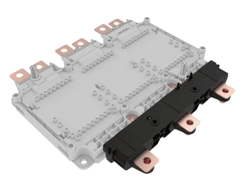
- The HAH3DR S07/SPx versions are specifically designed to fit within an inverter module such as the Infineon HybridpackTM Drive, with press-fit connection to the gate driver board.
- The HAH3DR S0x versions are designed to fit on thick busbars and available with a cable connector. S0x versions are specifically recommended to customers who look for a solution where the current sensor is located further away from the inverter module.
HAH3 – Features and benefits
Features
- Open Loop Hall effect current sensor
- Capable of measuring bidirectional AC and DC current
- Galvanic isolation
- Up to 1500 A
- Low voltage application
- Unipolar +5 V DC power supply
- Maximum RMS primary admissible current: defined by the busbar, the magnetic core or ASIC T < +150 °C
- Operating temperature range: −40 °C < T < +125 °C
- Output voltage: fully ratiometric (in sensitivity and offset)
- Rugged against high dV/dt
- Compact footprint for IGBT and SiC inverter power modules
- Various mounting options
In addition to these features, each HAH3 tri-phase current sensor offers unique special features. Please refer to the respective datasheets to discover these specific characteristics.
Main Benefits
- Excellent accuracy
- Very good linearity
- Very low thermal offset drift
- Very low thermal sensitivity drift
- High frequency bandwidth
- No insertion losses
- Very fast delay time
- Excellent cross talk immunity
Typical applications of the HAH3 Series
HAH3 current sensors, known for their proficiency in measuring DC, AC, and pulse currents, are widely employed in various automotive settings.
Examples of these applications include:
- Starter Generators
- Traction Inverters
- HEV applications
- EV applications
- DC / DC converter
LEM HAH3 – Download & Technical Characteristic
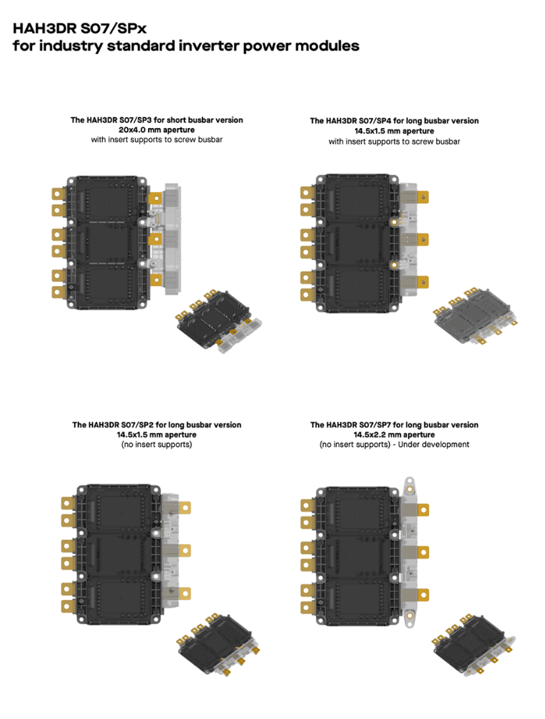
Zoom on HAH3DR S07/SPX and HAH3DR S0X
HAH3DR S07/SPX FOR IGBT AND SIC INVERTER MODULES
Lead pitch, busbar opening, mounting holes, package height and press-fit connection to the gate driver board, the HAH3DR S07/SPx is designed to perfectly fit standard inverter modules such as Infineon’s HybridpackTM Drive package and other pin-to-pin compatible modules.
The HAH3DR S07 is available in different versions to address specific mounting requirements:
HAH3DR S0X FOR VARIOUS BUSBAR CONFIGURATIONS
The HAH3DR-S06, S0A, S0D, S0E, S03/SP4 allow for current measurement on different configurations of busbar shape, thickness, and pitch. They also feature a cable connector for direct connection of the sensor output to a control board which may be located further away from the inverter. The larger busbar aperture allows to isolate the busbar with enough clearance and creepage with an airgap or with an additional insulating layer depending on the requirement.
The HAH3DR S00/SP4 offers a through hole connection to the gate driver board if located right on top of the sensor.

Example of busbars inserted into the HAH3DR S03/SP4, insulated with airgap or with insulation layer.

Example of busbar isolation with an airgap (left and right busbars) and with an insulating layer (center busbar)
HAH3 Sensors – ASK FOR SAMPLES / QUOTATIONS
Looking to receive samples or a quotation? Please click on the contact button below and provide us with the information you need on this product series. Our sales team will get back to you shortly.