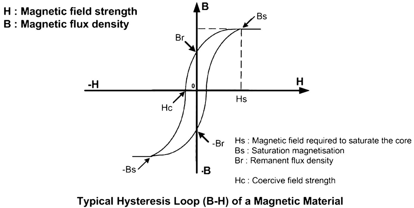
Why are transducers subject to core losses?
The magnetic material and core design as well as the spectral contents of the current amplitude versus frequency define the level of core losses. They are caused by the enclosed area within the hysteresis cycle, shown on the figure below.
Which parameters must be considered when choosing a transducer?
Take into account all aspects of the application
All aspects of an application must be taken into account for the selection of the transducer and system design, with particular attention to the following:
What is the transformation ratio?
The rated transformation ratio K is the ratio of the rated primary voltage or current to the rated secondary voltage or current. For closed loop current transducers, the turns ratio NP/NS is approximately the reciprocal of KR. For example, a turns ratio of 1:1000 implies approximately 1000 secondary turns (KR = 1000) and a secondary current of 1mA with a single primary turn carrying 1A.
What is the current derating versus frequency?
Because of the core losses in high frequency applications, the current shall be reduced in order to keep the transducer losses constant. Due to the complexity of the core geometry, the dependence of the core losses with the square of frequency, the square of magnetic flux density and the power dissipation by the housing, it is extremely difficult, if not impossible, to compute or to simulate the RMS current derating versus frequency.
What is the current consumption IC ?
It is the maximum current consumption of transducer’s electronics at the specified supply voltage when the primary signal is nil, added to the secondary current IS . This parameter is applicable only to the transducers with current output.
What does “di/dt accurately followed” mean?
Used to characterize dynamic behavior of a transducer and its ability to follow fast changes in primary current, “di/dt accurately followed” is the variation of primary current for which the response time does not exceed 1 ms at 90% of IPN.
What are the limits of measuring resistor (RM, RB)?
The measuring resistor has to be within a defined range to allow a safe and optimum operation of the transducer.
What are the advantages of transducers using an ASIC?
The ASIC (Application Specific Integrated Circuit) is, as the name indicates, an integrated circuit designed to provide several specific functions in one package.
The advantages are that it offers:
- Improved overall accuracy
- Lower cost
- Smaller size
- Customized functions
- Improved behavior in disturbed environments
- Improved quality level (reliability, aging)
What are partial discharge phenomenona explained?
A partial discharge is an electric discharge which occurs in a portion of an insulated area often in voids.
As a consequence of high temperature and emission of ultraviolet radiation generated by small electric arcs in the voids, the insulation layer is degraded. Gradually, small cavities increase and arcs begin to develop inside these cavities. The final step is a complete breakdown between the primary and the secondary parts of the transducer.
What are clearance and creepage distances?
Several international standards specify safety requirements applicable to the equipment included in their scope, with the main purpose to ensure that hazards to the operator, with respect to electrical, thermal and energy safety considerations are reduced to a tolerable level.