Addressing the current sensing challenges in automotive motor control
Why BEVs Are Revolutionizing Automotive Engineering
It is now widely accepted that battery-run electric vehicles (BEVs) are better for the environment compared to those of internal combustion engines (ICE).
From an engineering perspective BEVs are quicker to design since they contain fewer parts, no complex fluid mechanics and proven electronics. And, once operational, their software can be updated over the air (OTA).
From the end user’s standpoint, BEVs are efficient and more sustainable, emitting no fumes, leaks or vibrations, and with long-term operational costs now on a par with that of ICE vehicles.
As the electronics industry continues to innovate and address various design and technology challenges, BEV systems stand to benefit. A typical example is the easier and cheaper access to silicon carbide (SiC), a material that helps with thermal management since it produces lower losses.
With advanced semiconductor prices dropping, and with a thriving pool of competitors, devices for BEV systems are getting smarter, more optimised and cheaper, further encouraging the widespread adoption of electric vehicles.
How Current Sensors Enhance Safety and Performance in EV Motor Control
BEVs are electrical beasts and current flows through their ‘veins’ - from the battery management and motor control to the on-board chargers (OBC), and more. Managing this current is crucial, to optimally run these vehicles and to avoid safety hazards; for this, current sensors are used.
Current sensors monitor and accurately measure the current flowing through the motor, enabling its proper operation, but they also protect the system and the user.
In motor control, current is measured to effectively manage and regulate the motor’s torque and speed. To ensure that the inverter sends the right level of current into the motor, the output of the current sensors is fed into the inverter’s control loop.
The current sensor also protects the hardware from current fluctuations and runaway. Too much current can damage components like transistors or busbars, potentially causing irreversible damage. The sensor monitors the current and triggers a system alarm, or even shutdown, if not within certain limits. Thus, it is important that the current sensors are highly accurate.
To guard against harmful events, a functional safety strategy – also built on current sensors – ensures the vehicle can get into safe mode in case of hazardous events.
In a three-phase motor, each phase has its own, independent current sensor at the output of the inverter, to monitor the current and ensure its sum is always zero. Two current sensors can be sufficient here, with the current in the third phase being derived from the sum of the other two phases. For added system safety and reliability, designers tend to use three current sensors, since the first ‘rule’ of functional safety is redundancy.
Key Applications and Design Challenges in Electric Motor Systems
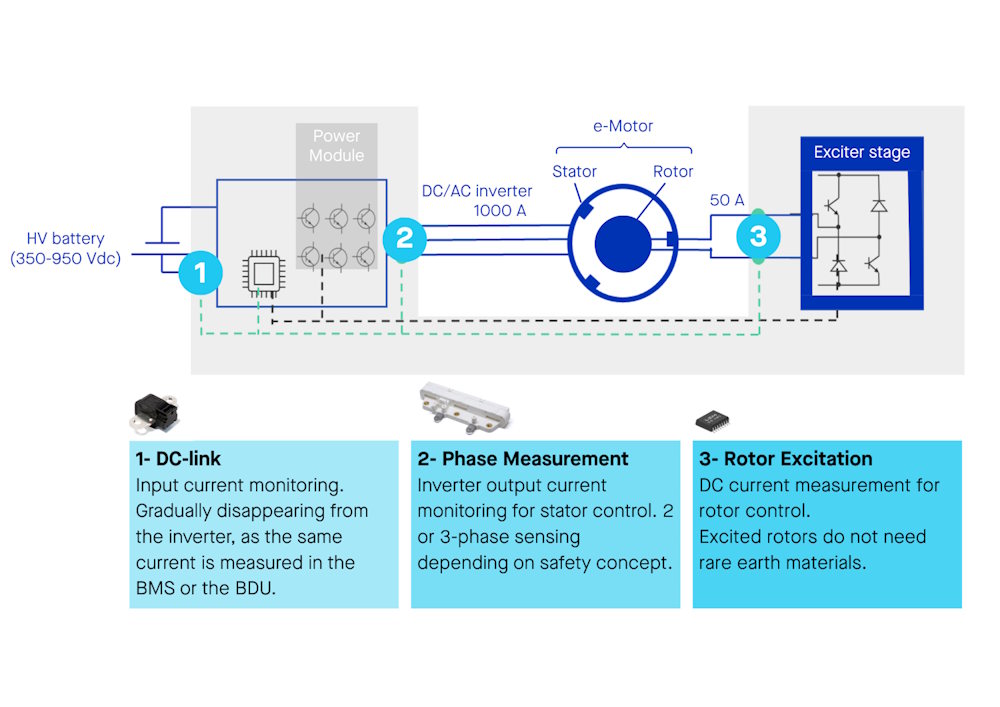
Figure 1: A typical motor control application with sensor positioning
Figure 1 shows the three areas where sensors are needed in a motor control application. These can be off-the-shelf (OTS) or custom sensors, with both types readily offered by LEM.
- The DC voltage from the battery pack must be kept stable for the system. This is the job of the DC link section, consisting of capacitors. It is an important stage to monitor and measure current, but, as a section, its function is gradually being replaced by either the battery management system or the battery disconnect unit. LEM offers various types of current sensors for this stage, with different mechanical form factors, including its single-phase, HSNDR, HSTDR, HAM and HAH1 devices.
- In the electric motor, the inverter's output current drives each phase of the motor, to create a rotating magnetic field that powers the motor's rotation. The inverter's current manages the motor's torque and speed by controlling the frequency and amplitude of the current delivered to each phase, and for this current sensors are required. Depending on the OEM’s safety approach, two- or three-phase sensing devices can be used here. For minimal footprint and lowest costs, mechanical integration is a way forward. LEM offers a portfolio consisting of HAH2 for two-phase, HAH3 for three-phase, as well as custom current sensor designs.
- At the rotor excitation stage the objective is to measure the direct current to control the wound rotor. For this stage, LEM’s HMSR, GO and advanced integrated current sensors (expected this year) are the perfect solution.
For all these stages, miniaturisation is key, with semiconductor innovation bringing better, smarter and cheaper sensors. LEM has responded with its Current Sensor IC range, which offers many capabilities in a small footprint.
When developing new current sensing devices, engineers always aim to make them smaller, smarter and cheaper.
Another way to achieve all of this is by increasing the power density of the sensing unit through integration.
An integrated sensing module offers best lifetime performance due to a combination of end-of-line full calibration that allows plug-and-play implementation, best mechanical and electrical coupling, high accuracy thanks to magnetic concentration, and good crosstalk suppression thanks to the magnetic core. However, this solution can be bulky and expensive.
Other current sensor design choices include the C- or U-shaped types, however, these require more R&D effort and in-house development, yet delivering mixed results, including:
- Mechanical integration uncertainties that over time can introduce mechanical tolerance errors, as well as coupling errors.
- A complex calibration stage for the inverter; and
- Higher costs because of the additional R&D resources required.
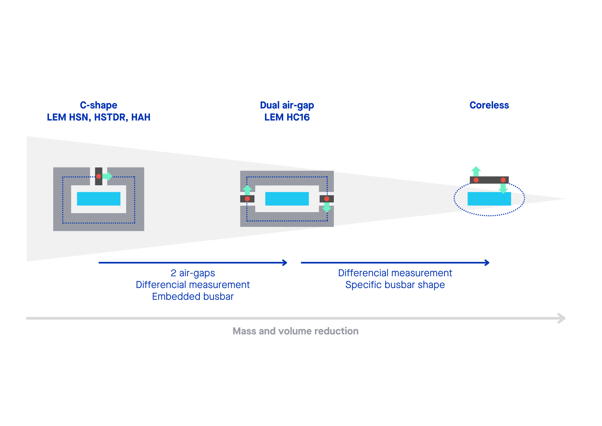
Figure 2: Current sensor evolution
At present, the industry is focusing on greater integration and coreless designs, for reduced footprints and costs and easier design-in; see Figure 2. These will be standalone, standard-packaged semiconductors that require very little assembly and integration effort. Still, this approach requires good mechanical design to guarantee coupling and eliminate crosstalk.
Ongoing semiconductor innovations are expected to make a crucial difference, bringing coreless design to reality. A true coreless design removes the magnetic core from the current sensor module, and is the best option to reduce the total package size, but imposes new form factors and requires solving performance challenges: Better accuracy requires better coupling, less crosstalk, better linearity over a very large current range, which in turn requires better semiconductors, better mechanical concepts, greater collaboration with OEMs, and so on.
Another big challenge is providing the right safety level whilst keeping costs down. This can be addressed by integrating the diagnostics into the ASIC.
Overcoming Industry-Wide Challenges in EV Sensor Integration
Mechanical integration, safety and cost are crucial aspects of developing the perfect solutions for automotive motor control applications.
In these applications, there’s ample Z-axis vibrations and crosstalk, and the sensors can suffer from inaccurate calibration. There could be bandwidth limitations, and issues with secondary connections to the control board.
Integrated design at the power module helps here, guaranteeing mechanical and electrical coupling, optimising calibration, and with press-fit secondary connection to the control board.
LEM works directly with OEMs and Tier 1 suppliers to co-design solutions, to address any challenge that may arise in creating the required automotive motor control system. Through its approach to mechanical integration and with an efficient manufacturing process, it can offer more accurate calibration of the sensors. This may require the calibration to be managed by the inverter manufacturer at system level.
Collaborating closely with OEM and Tier-1 companies’ R&D teams from the outset will help achieve the best integration of the current sensing function into the system from the start. Added components at the manufacturing level will not be required, and calibration will be accurate and guaranteed from the beginning, since the sensor is part of the system and has been calibrated specifically for the task.
One example is the collaboration between LEM and Semikron Danfoss where the current sensor is embedded and calibrated in the frame of a standard power module.
In parallel of coreless innovation and partnerships such as the one with Semikron Danfoss, LEM continues to optimise its existing current sensors, keeping them highly competitive without compromising their quality or performance. It had recently redesigned its HC5 device, now known as HC5FL.
To keep its product portfolio at the pinnacle, LEM has made assembly leaner, optimised the magnetic core, and is planning a new ASIC this year at a competitive price, whilst ensuring device performance.
Custom vs Off-the-Shelf Current Sensors: Choosing the Right Solution
Finding the right partners, those who anticipate customer needs at an early stage and provide thought-through, high-performing solutions, will help companies accelerate their design time and shrink the time-to-market curve. LEM has built its expertise in the motor control area since the 1990s, changing and adapting its portfolio in tune with the market. Its continual market research and close cooperation with its customers has helped it anticipate the market needs even when trends are still in their infancy.
More than 50 years of experience and application knowledge give LEM expertise in key domains like mechanical design, sensing technologies, sensor calibration, ASIC design and software development. This allows LEM to deliver on custom specifications, and by working closely with customers’ internal R&D teams co-develop the solutions they need.